
A Selection Guide for DTL Series Heat Exchangers This is your guide to sizing a
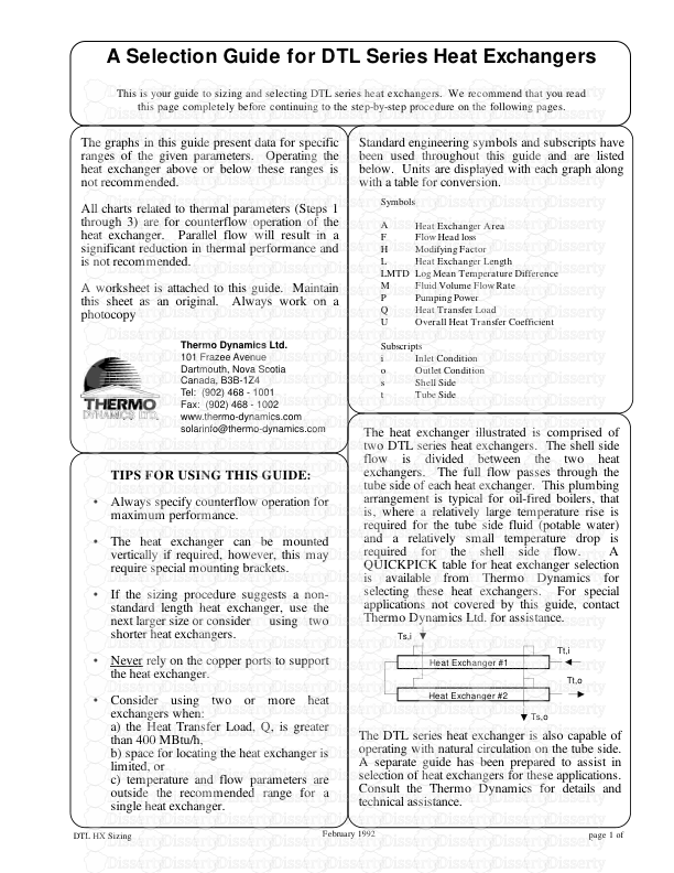
A Selection Guide for DTL Series Heat Exchangers This is your guide to sizing and selecting DTL series heat exchangers. We recommend that you read this page completely before continuing to the step-by-step procedure on the following pages. Heat Exchanger Area Flow Head loss Modifying Factor Heat Exchanger Length Log Mean Temperature Difference Fluid Volume Flow Rate Pumping Power Heat Transfer Load Overall Heat Transfer Coefficient Inlet Condition Outlet Condition Shell Side Tube Side TIPS FOR USING THIS GUIDE: Always specify counterflow operation for maximum performance. The heat exchanger can be mounted vertically if required, however, this may require special mounting brackets. If the sizing procedure suggests a non- standard length heat exchanger, use the next larger size or consider using two shorter heat exchangers. Never rely on the copper ports to support the heat exchanger. Consider using two or more heat exchangers when: a) the Heat Transfer Load, Q, is greater than 400 MBtu/h, b) space for locating the heat exchanger is limited, or c) temperature and flow parameters are outside the recommended range for a single heat exchanger. The heat exchanger illustrated is comprised of two DTL series heat exchangers. The shell side flow is divided between the two heat exchangers. The full flow passes through the tube side of each heat exchanger. This plumbing arrangement is typical for oil-fired boilers, that is, where a relatively large temperature rise is required for the tube side fluid (potable water) and a relatively small temperature drop is required for the shell side flow. A QUICKPICK table for heat exchanger selection is available from Thermo Dynamics for selecting these heat exchangers. For special applications not covered by this guide, contact Thermo Dynamics Ltd. for assistance. Ts,i Tt,i Ts,o Tt,o Heat Exchanger #1 Heat Exchanger #2 The graphs in this guide present data for specific ranges of the given parameters. Operating the heat exchanger above or below these ranges is not recommended. All charts related to thermal parameters (Steps 1 through 3) are for counterflow operation of the heat exchanger. Parallel flow will result in a significant reduction in thermal performance and is not recommended. A worksheet is attached to this guide. Maintain this sheet as an original. Always work on a photocopy Symbols A F H L LMTD M P Q U Subscripts i o s t Standard engineering symbols and subscripts have been used throughout this guide and are listed below. Units are displayed with each graph along with a table for conversion. THERMO D YNAMICS LTD . page 1 of 6 DTL HX Sizing • • • • • The DTL series heat exchanger is also capable of operating with natural circulation on the tube side. A separate guide has been prepared to assist in selection of heat exchangers for these applications. Consult the Thermo Dynamics for details and technical assistance. 81 Thornhill Drive Dartmouth, Nova Scotia Canada, B3B 1R9 Tel: (902) 468-1001 Fax: (902) 468-1002 February 1992 Thermo Dynamics Ltd. 101 Frazee Avenue Dartmouth, Nova Scotia Canada, B3B-1Z4 Tel: (902) 468 - 1001 Fax: (902) 468 - 1002 www.thermo-dynamics.com solarinfo@thermo-dynamics.com STEP 1: Known Operating Parameters Consider the following when allocating the heat transfer fluids: Fluids under high pressure and/or corrosive fluids are generally circulated through the tube side. Chemical cleaning is recommended. Mechanical cleaning is not possible with DTL Series heat exchangers. High viscosity fluid should be circulated on the shell side. Propylene glycol, for example, has higher viscosity than water. Head loss on the tube side of the heat exchanger is generally ten times less than the shell side head loss for equal flow rates. Make a note of the following parameters in the boxes provided on the Worksheet. Shell Side Inlet Temperature, Ts,i Tube Side Inlet Temperature, Tt,i Heat Transfer Load, Q Shell Side Outlet Temperature, Ts,o Tube Side Outlet Temperature, Tt,o Use the figures given here to determine Ts,o and Tt,o from the flow rate or vice versa. The figures are for water as the working fluid. For 50/50 or 40/60 propylene glycol/water mixtures multiply (To-Ti) by 1.1. If To - Ti gives a negative result then simply drop the negative sign when using the graphs at the right. Always operate within the range of parameters provided. This will ensure that flow is turbulent but not excessively noisy. Tt,o Ts,i Ts,o Tt,i • • • • 1.1 1.2 To - Ti (°F) 0 20 40 60 80 100 120 140 160 180 200 2 3 4 5 6 7 8 9 10 Ms or Mt (USGPM) 400 300 200 160 120 80 40 20 Heat Transfer Load Q (MBtu/h) From kW IGPM kg/s °C To MBtu/hr USGPM IGPM °F Multiply by 3.4123 1.2 13.19 1.8 Unit Conversions To - Ti (°F) 0 10 20 30 40 50 60 70 80 90 10 15 20 25 30 35 40 45 50 Ms or Mt (USGPM) 400 300 200 160 120 80 Heat Transfer Load Q (MBtu/h) page 2 of STEP 2: The Overall Heat Transfer Coefficient Estimate the Degree of Fouling: Light Fouling - Distilled water Moderate Fouling - Treated boiler feedwater, below 120°F (50°C) Heavy Fouling - Treated boiler feedwater above 120°F (50°C), River water, Well water, propylene glycol /water. Estimate the overall heat transfer coeffient, U, from the appropriate graph using the shell side flow rate, Ms. Two cases are presented (A and B). Both are valid for forced circulation on the shell and tube sides only. If the hotter fluid is circulated on the tube side, then increase U by 10%. Make a note of U in the box provided on the Worksheet. 2.1 2.2 Calculate the ratio of shell side to tube side flow rates, Ms/Mt. Estimate the factor, F, using the flow rate ratio and make a note in the box provided on the Worksheet. Ms (USGPM) 100 150 200 250 300 350 400 450 0 5 10 15 20 25 30 35 40 45 50 U (Btu/h-ft2-°F) Tube Side: Water, Forced Circulation Shell Side: PG/Water 50/50, Forced Circulation B 2" Ø 3" Ø 4" Ø Light Medium Heavy 10 0 0.1 0.2 0.3 0.4 0.5 0.6 0.7 0.8 0.9 1 0 1 2 3 4 5 6 7 8 9 F Ms/Mt 2" Ø 3" Ø 4" Ø 4" Ø U (Btu/h-ft2-°F) 2" Ø 3" Ø 0 100 200 300 400 500 600 700 0 5 10 15 20 25 30 35 40 45 50 Ms (USGPM) Tube Side: Water, Forced Circulation Shell Side: Water, Forced Circulation A Light Medium Heavy From IGPM Btu/h-ft2-°F To USGPM W/m2-K Multiply by 1.2 5.68 Unit Conversions 2.3 2.4 page 3 of STEP 4: Heat Exchanger Length A = F x U x LMTD Q x 1000 STEP 3: Log Mean Temperature Difference ˘ T2 (°F) ˘ T1 (°F) LMTD (°F) 0 20 40 60 80 100 120 140 160 180 200 0 20 40 60 80 100 120 140 160 180 200 185 165 145 125 105 85 65 45 25 15 5 Area (ft2) Length (ft) 3 4 5 6 7 8 9 10 11 12 0 3 6 9 12 15 18 21 24 27 30 33 36 39 42 45 4" Ø 3" Ø 2" Ø Area (ft2) Length (ft) 3 4 5 6 2.5 3.0 3.5 4.0 4.5 5.0 5.5 2" Ø From m m2 To ft ft2 Divide by 0.3048 0.0929 Unit Conversions Calculate ˘ T1 and ˘ T2 using the equations provided on the Worksheet. If the above calculations result in a negative value for ˘ T1 and/or ˘ T2 then simply drop the negative sign prior to using the graph at the right. Estimate LMTD from the graph. Make a note of LMTD in the box provided on the Worksheet. 3.1 3.2 From °C To °F Multiply by 1.8 Unit Conversions Calculate the required heat exchanger area using the formula given above. Record the result in the box provided on the Worksheet. Use the heat exchanger area, A, and shell diameter, to determine the heat exchanger length from the appropriate graph. Record the heat exchanger length in the box provided on the Worksheet. 4.1 4.2 page 4 of Use the graphs below to estimate the head loss for the shell side and tube side flow through the DTL series heat exchangers. The head loss is useful for pump sizing and estimating the operating costs of the heat exchanger. Given the heat exchanger length, shell diameter and corresponding flow rates, estimate the head loss and record it in the box provided on the Worksheet. A procedure for estimating the operating costs of the heat exchanger is given on the Worksheet. Note: The graphs below are not valid for natural circulation flow. STEP 5: HEAD LOSS 12' 6' 3' 6' 3' 0 5 10 15 20 25 30 35 40 45 50 0 5 10 15 20 25 30 35 40 45 50 Hs (ft) Ms (USGPM) 2" Ø 3" Ø 4" Ø 9' 6' 3' 0 1 2 3 4 5 6 7 8 9 10 0 uploads/Litterature/ hx-sizing-guide.pdf
Documents similaires


-
127
-
0
-
0
Licence et utilisation
Gratuit pour un usage personnel Attribution requise- Détails
- Publié le Mar 31, 2022
- Catégorie Literature / Litté...
- Langue French
- Taille du fichier 0.1293MB